Open Air Choke Balun
By Dave Jordan, WA3GIN
We hear a lot and see many articles about using balun technology to reduce RFI, provide better matching to balanced antennas like ½ wave dipoles or to reduce feed-line interaction with yagi and vertical antennas. There are naming conventions for baluns as well, such as voltage, current and open air choke baluns. This article is a do-it-yourself construction brief for the open-air type balun. For more details about baluns go here: http://vk1od.net/balun/concept/VoltageCurrent.htm
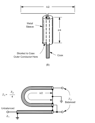
Above are two baluns from the ARRL Handbook, neither uses a magnetic core. The second also performs 4:1 impedance transformation. Classify each as a Voltage Balun, Current Balun, or neither.
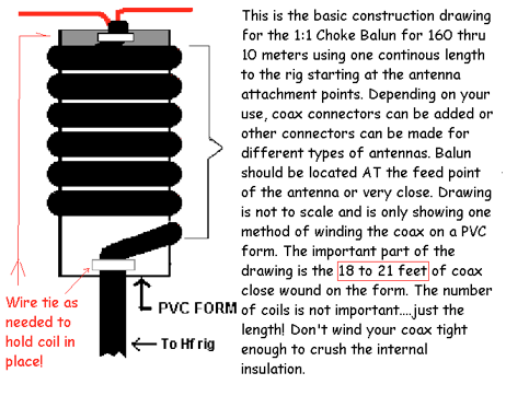
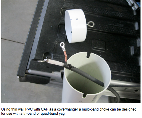
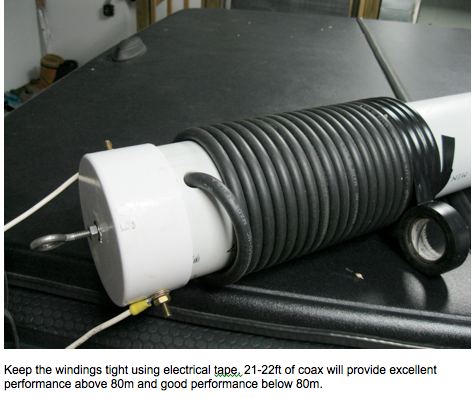
Enter the open-air choke balun from N4UJW:
Introduction …
A balun’s purpose is to allow connecting a balanced, (e.g., a dipole or driven element) to an unbalanced line such as coax which is not balanced, thus the name, Balun. The 1:1 choke “balun” is not actually a balun. It’s function is to help eliminate rf currents from flowing on the outside of coaxial cable using the principle of choke action. Another “name” for it is the air choke.
In transmitting antennas, this is accomplished by presenting a high impedance (resistance), to RF currents flowing outside the coax shield. This forces currents in each side of a driven elements to be equal. This is especially important in beam antennas because it prevents distortion of the beam’s pattern caused by unequal currents in the driver(s). In a simple dipole, the balun (choke), assures that the dipole, and not the feed line, is doing the radiating!
When you connect center fed antennas, like dipoles, V’s, triangles, yagis, rhombics, loops and so on, to coaxial cable, unless care is taken, it is not difficult to end up with feeder radiation. Not only can the loss in power be quite significant, but the radiation characteristics of the antenna system will also be seriously compromised.
In laymen’s terms, it won’t be what you are expecting from the pattern of your antenna.
As the feedline becomes part of the antenna, currents can flow from the line into the mains and on TV cables, metal masts and yagi booms, causing a variety of EMI problems that can be very difficult to trace. Frequently these problems are simply due to unbalance – and the solution is the humble air choke.
If an antenna system is fed at center with a parallel conductor line (provided that correct installation procedures are followed) balance will be maintained, USING A BALUN, with currents in equal and opposite phase canceling each other out.
When the connection is to a coaxial cable, WITHOUT A BALUN, this cannot occur because currents flowing inside the cable from the connection to the inner conductor are separated from those flowing on the outside from the connection to the shield, and the result is unbalance causing feeder radiation. However, if the two electrical circuit elements (antenna and coaxial cable) are coupled using a balan, balance will be maintained.
Enter … The Ugly Balun!
Category: Ham Projects

